WHAT IS
3D RAD?
CLICK HERE
TO FIND OUT!
RigidBody
RigidBody is a customizable solid object supporting collision detection and realistic physics simulation.
You can use your favorite 3d modeling application to create new rigid-bodies and add them to the RigidBody object library.
Your own 3d models are used by the RigidBody object as a reference to implement collision detection or determine mass distribution (which ultimately determines physics behavior). Please see this document for details.
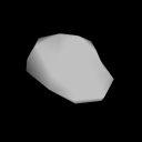
Run-time, a RigidBody object is usually invisible and its visual aspect is provided by a SkinMesh attached to it. However, in the Virtual Editor (and run-time, mainly for debug purposes) it is visualized via a placeholder-mesh.
The RigidBody can act either as a static object (for example a terrain or the walls in a dungeon) or as a dynamic object (a car body, an airplane fuselage, a bullet, a falling rock etc). Please see Total Mass parameter (below) for more.
The RigidBody object will be subject to physics laws as soon as the project is started. For example, if it is dynamic and it is linked to a G-Force and a Terrain object, it will fall and rebound realistically.
After adding a RigidBody object to your project, you can configure it by double-clicking it in the Object List.
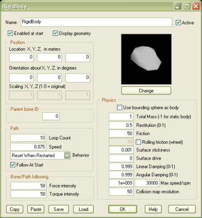
If this option is not checked, the rigid-body will only perform physics simulation when the object is shown by another object, like for example EventOnInput.
Note that physics is enabled by showing the object, instead of starting it, because being enabled, for a RigidBody object, doesn't just mean that its physics simulation is performed, but also that its placeholder geometry is rendered run-time. But see Display placeholder geometry for more.
Check this option to visualize the rigid-body's placeholder model, run-time. Note that the model is not shown if the object is disabled (see Enabled at start).
In the Virtual Editor you can only hide the placeholder mesh by right-clicking the item in the Object List.
When this value is non-zero, and the RigidBody object is linked to a SkinMesh which is bone-animated, the rigid-body will be attached to the SkinMesh's bone specified by the ID.
This feature can be used, for example, to achieve collision-detection and physics for a foot kicking a ball. See the example project called SkinMeshBoneRigidBodyDemo.3dr.
The bone ID must be a positive, non-zero integer. The first bone in the model is 1, the second 2 and so on. What bone corresponds to a certain ID depends on how the animated model was originally designed.
Note: the position of the attached RigidBody object is relative to the bone position when the animated model is in its initial pose. This may not be the default pose you see in the Virtual Editor. To see the initial pose of all animated SkinMesh objects in the scene, hold the [F] key pressed.
Note: this parameter can be modified run-time by using a script (see 'Internal Parameters' section, below). This allows you to detach the RigidBody object (bone ID = 0) or switch target bone. Note that this feature is only supported for RigidBody objects that are attached to a bone when the project starts.
If you attach the RigidBody object to a path by linking it to a Path object then it will try to follow the pre-defined course.
Note that the relative speed along a specific portion of the path depends on the number of nodes defined along the segment. In particular, the more nodes are defined, the slower the speed. This property allows you to accurately program speed variations.
When the RigidBody is attached to a bone or a Path, it will tend to follow the bone/path. You must tweak the Force intensity and Torque intensity factors to achieve an accurate following behavior for your specific object.
The remarkable advantage in mixing bone/path following with physics this way (instead of using SkinMesh object's bone/path following functionality for example) is that your object can interact realistically with the environment (collisions, forces, joints) while traveling along the pre-defined bone/path course.
This simplified 'solid' volume is faster to process. It is automatically created from the bounding sphere of the placeholder mesh and it is recommended over the spg/ply-based version where accuracy for collision detection and simulation is not required.
NOTE: setting masses too low can cause very instable simulations and even software crashes, especially when multiple RigidBody objects are connected by using Joint objects to form complex systems. Messes below 1.0 are usually not recommended, unless bodies are very simple, like for example single spheres.
IMPORTANT! Setting this value to -1 will make the object static (infinite weight). This is typically used for scenery elements, like terrain, buildings, trees and so on.
Note that when two objects collide, the actual restitution is the average of the restitution factors of the two objects.
Note that when two objects collide, the actual friction depends on the factors of both objects.
The bigger the value, the stronger the repulsion force. Negative values are valid.
On collisions, excessive speed or spin may cause inaccurate physics simulation, severe frame-rate drops and even crashes. To achieve solid simulations, set these parameters to the lowest values allowed by your game design.
Bigger values tend to affect frame-rate. Smaller values tend to produce better frame-rates, but they increase initialization time (when you close the property dialog).
Warning! A resolution too small for a big model can produce an incredibly long initialization time and huge data files on your hard disk!
NOTE: this parameter is ignored if the RigidBody is dynamic (collision detection model made of spheres).
For information about the remaining controls, please click here.
The following internal parameters can be accessed by using event objects like EventOnValue or Script: