WHAT IS
3D RAD?
CLICK HERE
TO FIND OUT!
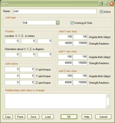
Joint
The Joint object allows you to link objects together to make systems as simple as a pendulum or as complex as a ragdoll.
Joint's rotational limits can be set and angular forces can be defined to simulate motors and advanced mechanisms.
The joint will act on the two objects linked to it, at the Joint object location, which you can set visually, in the Virtual Editor.
Joint object orientation is also important as certain joint properties, like rotational limits, motors and axes, may depend on Joint object orientation.
Note that the two objects linked to the joint must support physics. RigidBody, Ball, Car, can all be used with joints for example, while SkinMesh cannot.
Multiple Joint objects can be used to connect multiple RigidBody objects and create any kind of system.
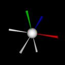
When working with joints, keep in mind that the small blue axis of the Joint object item is the local Z axis.
When the joint is in a slider mode, the blue axis is the line along which the slider will move, with blue axis direction being the positive direction.
The blue axis is also the reference for the hinge mode, where it is the axis about which the swiveling happens.
Positive rotations are always counterclockwise, if you look at the colored axis, when it points toward your eye.
A ball joint acts like a single point about which the secondary object can rotate freely, unless limits are set (see below).
A fixed joint completely glues two objects together, blocking any relative movement. Note that fixed Joint position is irrelevant.
A fixed (fast) joint is a fixed joint that works for objects that have identical orientation only. This version is much faster to process.
A hinge joint acts like an axis about which the secondary object can rotate. This is always the local Z axis for the Joint object (blue axis).
A slider joint acts like a line along which the secondary object can move. This is always the local Z axis for the Joint object (blue axis).
If this option is not checked, the junction will be enabled only when the Joint object is started by another object, like for example EventOnInput.
In this case, the joint location will be relative to the reference object (see Relationships, below).
That is, while the application point for the reference object is the relative location you defined in the Virtual Editor, for the second object (body B), the application point will depend on object's location at the time of Joint activation.
Where applicable, depending on joint type, for each local axis of the Joint object (red arm is +X, green is +Y, blue is +Z) you can define the rotational limits, in degrees.
Setting these limits to -180 and +180 actually disables the stop.
NOTE: due to simulation limitations, you may not be able to completely block rotations about all axes by setting rotational limits alone. The recommended workaround is using three Joint objects with no rotational limits set instead.
NOTE: rotational limits have no effect if one of the two linked objects is static (infinite total mass, see RigidBody). To overcome this limitation, set the RigidBody total mass to a very high value (eg 2,000,000,000), and use and additional Joint (fixed type) to keep RigidBody in place.
NOTE: rotational limits make the simulation more complex to compute and therefore may affect frame-rate on slower computers.
Important! Joint stops simulation is based on Euler angles math and therefore it has the following limitation: you cannot set Z-axis limits below -90 or above 90, unless X-axis limits or Y-axis limits (or both) are zero. Failing to do so may severely disrupt the simulation.
NOTE: for slider joints, limits are in meters, from the Joint object location, along its local X axis.
These two parameters determine the behavior of the stop (see Angular limits, above).
The bigger the strength factor, the stronger the stop. A strong stop will resist torques more than a weak stop. By default, stop strength is 40000 (very strong).
The bigger the hardness factor, the harder the stop. A soft stop will 'absorb' torques in a spongy way. By default, stop hardness is 150000 (very hard).
You can achieve soft stops by setting both strength and hardness to lower values (for example 5.0 and 0.01 respectively).
Where applicable, depending on joint type, you can apply a torque to the linked objects, about each local axis of the Joint object.
The spin factor is the reference angular velocity the motor will try to reach and keep, in degrees per second.
The torque factor is the angular force applied to reach and keep the specified spin. Setting this value to zero actually disables the motor.
NOTE: motors have no effect if one of the two linked objects is static (infinite total mass, see RigidBody). But see above for a workaround.
NOTE: for slider joints, motor parameters are speed (in meters per second) and force, as they are linear quantities.
This list defines how the Joint object relates to the objects linked to it. The following relationship types are supported:
NOTE: Specifying more than one single object as body A or more than one single object as body B is not recommended. Resulting behavior is undefined.
The following internal parameters can be accessed by using event objects like EventOnValue or Script: